Vortex Generator Research (NACA 2412)
Verified a 76% increase in stall angle by optimizing vortex generator placement, in a self built wind tunnel.
Scope: Co-researcher, designed and tested 7 of 14 vortex generator configurations, with research partner Nathan Xia. Tools: self built low speed visualization wind tunnel, FDM 3D printing, TinkerCAD. Grant funded.
This research optimized the placement and spacing of vortex generators (VGs) on a NACA 2412 airfoil to delay boundary layer separation and raise the stall angle of attack. The NACA 2412 is common on low speed general aviation aircraft such as the Cessna 172, where VGs are far less developed than on high speed commercial wings. The work was completed with a research partner, Nathan Xia. Across the study we designed and tested 14 VG configurations, of which I owned 7, and it was later written up as a formal paper.
Research Question
How does the long gap spacing (2, 3, 4, 5 mm) and chordwise location (10, 15, 20, 25 percent) of VGs on a NACA 2412 airfoil affect its stall angle at low speed, at a Reynolds number below 2300?
Method
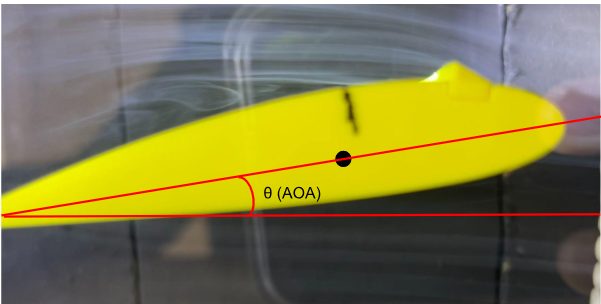
Testing used a low speed smoke flow visualization wind tunnel built from scratch, with a 7.5 by 34.0 by 12.0 cm chamber, an airspeed of 0.84 m/s, and a Reynolds number below 2300. Eight 75 mm chord airfoils were 3D printed in PLA, one control plus seven carrying VGs, with vane height, length, shape, type, and inflow angle held fixed so only long gap spacing and chordwise location varied. Angle of attack was raised until the separation point reached 30 percent chord, the approximate point of maximum thickness on a NACA 2412, recorded visually with incense smoke over three trials per airfoil, reading the protractor only after separation to remove bias.
Results
Parabolic fits to the averaged data (R squared above 0.93 for both) located the optima and quantified the effect:
- Optimal chordwise location of 17.2 percent chord raised the separation angle to 11.8 degrees, a 76% increase over the control airfoil at 6.7 degrees.
- Optimal long gap spacing of 3.6 mm raised the angle to 7.5 degrees, a 12% increase, showing placement matters far more than spacing.
- Poorly chosen VGs hurt: 2 mm and 5 mm spacings gave 5.2 and 5.7 degrees, below the bare airfoil, consistent with added parasitic drag outweighing the mixing benefit.
On scope and validity: the tunnel runs at a Reynolds number below 2300, a low speed tabletop regime. These results are a proof of concept, not a direct prediction of flight scale performance. Vortex generator behavior does not extrapolate cleanly to the far higher Reynolds numbers of an aircraft in cruise.
Better separation control on beginner aircraft carries potential efficiency implications only if validated at flight Reynolds numbers. No fuel savings or efficiency figure is claimed here; efficiency was the motivation for the study, not a measured result.
Reflection and Next Steps
The headline result is the verified 76% increase in stall angle from placement optimization alone. Natural next steps are measuring lift and drag coefficients directly, and testing at higher Reynolds numbers.
This project enhanced my ability to conduct experimental research, analyze data, and communicate technical findings.